Quick Answer
0201 and 01005 SMT assembly requires tighter control of PCB pad design, solder paste printing, stencil aperture, component storage, pick-and-place accuracy, placement force, reflow profile, AOI settings, rework limits and first article inspection. These components are small enough that ordinary SMT assumptions can create tombstoning, skew, missing parts, solder bridging, poor wetting or inspection escapes.
Key Definition
0201 and 01005 are ultra-small passive component package sizes used when product miniaturization, high-density layout or RF performance requires very compact board space. In PCBA manufacturing, the challenge is not only whether the part can be placed. The real question is whether the factory can hold a repeatable process window from solder paste printing through inspection and batch release.
Keep Best treats miniature-component assembly as an SMT process-control topic connected to PCBA manufacturing services, quality management, DFM engineering support, RFQ submission, OEM manufacturing, ODM engineering, box build assembly and industry PCBA solutions.
Why 0201 and 01005 Components Need Special Process Control
Small passive components reduce board area, but they also reduce tolerance for process variation. A slight solder paste imbalance, board warpage, nozzle issue, placement offset or reflow imbalance can shift the result from acceptable yield to repeated defects. For overseas buyers, this is a quotation issue as much as a production issue. The supplier needs to know whether the board requires ultra-small-component capability before quoting SMT labor, stencil strategy, inspection coverage and rework assumptions.
The requirement should be included in the controlled RFQ package alongside the RFQ file checklist for overseas PCB assembly buyers, the DFM report issues closure guide and the first article inspection checklist for low-volume PCBA.
SMT Assembly Process Requirements
1. PCB Pad and Solder Mask Design
The board layout must support stable solder paste release and self-alignment. Pad geometry, solder mask clearance, trace entry, copper balance and spacing around adjacent components should be reviewed during DFM engineering support. Pads that are too large, too small or uneven can create tombstoning, skew or insufficient solder. If multiple ultra-small packages are clustered together, solder mask and copper design become even more important.
2. Stencil Aperture and Paste Volume
Stencil design controls how much solder paste reaches the pads. For 0201 and 01005 assembly, aperture size, shape, thickness, area ratio and paste release must be tuned to the package and board finish. Too much paste can create bridging or floating. Too little paste can create weak joints or open circuits. The stencil plan should be approved before production release, not adjusted only after defects appear.
3. Solder Paste Handling
Paste type, storage, thawing, mixing, stencil life, printing interval and humidity control matter more with miniature components. Poor paste condition can cause poor transfer, solder balls or inconsistent wetting. The supplier should define paste handling rules as part of the SMT process plan and link them to quality management.
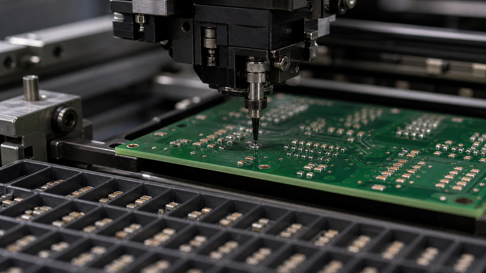
4. Pick-and-Place Accuracy
The placement machine must use suitable nozzles, feeder setup, vision recognition and placement force. For ultra-small parts, feeder vibration, nozzle contamination or slight board support movement can cause missing parts or offset placement. Buyers should ask whether the supplier has verified placement capability for the smallest package on the design.
5. Board Support and Panel Stability
Panel support affects printing and placement accuracy. Thin boards, dense layouts, heavy copper imbalance and small panel rails can increase movement during production. Panelization details should be reviewed with the SMT panelization rails and fiducials guide. Fiducials should be visible, clean and usable by the placement and inspection equipment.
6. Reflow Profile Control
Reflow profile must balance wetting, component stability and thermal stress. Miniature passive components can tombstone when the two terminations heat unevenly or when paste volume differs between pads. The process should define soak, peak temperature, time above liquidus and cooling assumptions for the board finish and component mix.
7. AOI, X-Ray and Visual Inspection
Inspection settings must be tuned for small package geometry. AOI should detect missing parts, offset, skew, polarity where relevant, solder bridging and suspicious wetting. Some defects may require microscope confirmation. Acceptance criteria should connect to IPC-A-610 Class 2 and Class 3 PCBA inspection where applicable.
8. Rework Limits
Rework on 0201 and 01005 components is more difficult and can damage pads, nearby parts or solder mask. The process plan should define whether manual rework is allowed, how many attempts are acceptable, and when a board should be scrapped or escalated. Low-volume projects should capture this in the first article inspection checklist.
Process Evidence Table
| Requirement | Evidence to request | Risk if missing | |---|---|---| | Pad design | DFM confirmation of pad, mask and spacing | Tombstoning, skew or solder imbalance | | Stencil plan | Aperture, thickness and paste-release strategy | Bridging, opens or unstable yield | | Paste control | Storage, thawing, print interval and humidity rules | Poor transfer or solder balls | | Placement setup | Nozzle, feeder, vision and force confirmation | Missing, shifted or rotated components | | Panel stability | Rails, fiducials and board support review | Print or placement offset | | Reflow profile | Approved thermal profile and board assumptions | Tombstoning or poor wetting | | Inspection | AOI program and microscope confirmation rule | Small defects escape detection | | Rework policy | Allowed method, attempt limit and escalation rule | Pad damage or hidden reliability risk |
Buyer Action Checklist
- Mark 0201 and 01005 components clearly in the BOM and placement file.
- Ask the supplier to confirm SMT capability before approving the quote.
- Request DFM comments on pad design, spacing, panelization and fiducials.
- Confirm stencil aperture and solder paste assumptions before production release.
- Require first article evidence for placement, soldering and inspection results.
- Define whether AOI, microscope review, ICT, FCT or functional testing is required.
- Connect ultra-small-component risks to PCBA manufacturing services, quality management and RFQ submission.
What a Good Supplier Should Return
A strong supplier should return process-specific feedback, not only a unit price. The response should include manufacturability comments, stencil assumptions, placement capability, inspection plan, rework policy, test requirements, open risks and pilot-build recommendations. If the assembly also includes enclosure, cable or final product integration, the review should extend into DFMA versus DFM, OEM manufacturing, ODM engineering or box build assembly.
FAQ
Are 0201 and 01005 components suitable for every PCBA factory?
No. The factory must have suitable stencil control, placement accuracy, inspection setup and process discipline. The buyer should verify this capability before quotation approval.
What is the biggest risk in 0201 and 01005 SMT assembly?
The biggest risk is process-window instability. Small changes in paste volume, placement offset, board support or reflow can create repeated defects across the batch.
Should buyers request special inspection?
Yes. AOI settings and microscope confirmation rules should be defined for ultra-small components. If the board has critical circuits, functional testing or ICT may also be required.
Can small components be manually reworked?
Sometimes, but rework should be limited and controlled. Manual repair can damage pads or nearby components, so the supplier should define the rework method and escalation rule.
What files should buyers send for accurate quotation?
Send Gerber, BOM with package details, placement data, assembly drawing, panel data, test requirements, target quantity and any known miniature-component risks.