Key takeaways
- DFT is not only adding test points. It is designing how production defects will be found, isolated and corrected. - ICT is strongest for manufacturing defects; FCT is strongest for product behavior. They should be planned together. - Test access, fixture design, programming control and acceptance limits should be decided before PCB layout release. - A buyer should ask what each test can detect and what remains outside the test coverage.
Why DFT should start before layout release
Design for Testability is often discussed too late. If test planning starts after the PCB layout is finished, the manufacturing team may discover that key power rails have no accessible points, connectors block probe access, programming pads are too small or sensitive signals cannot be isolated. At that stage, the only options are compromise, manual testing or a layout change that delays the project. Good DFT starts during schematic and layout review.
For overseas PCBA buyers, DFT has a direct commercial impact. It affects fixture cost, test cycle time, failure analysis speed, repair cost and shipment confidence. A product may pass final function, but if the test cannot locate the defect efficiently, every failure becomes slow and expensive. In low-volume projects, this creates engineering delays. In higher-volume projects, it affects delivery and first-pass yield.
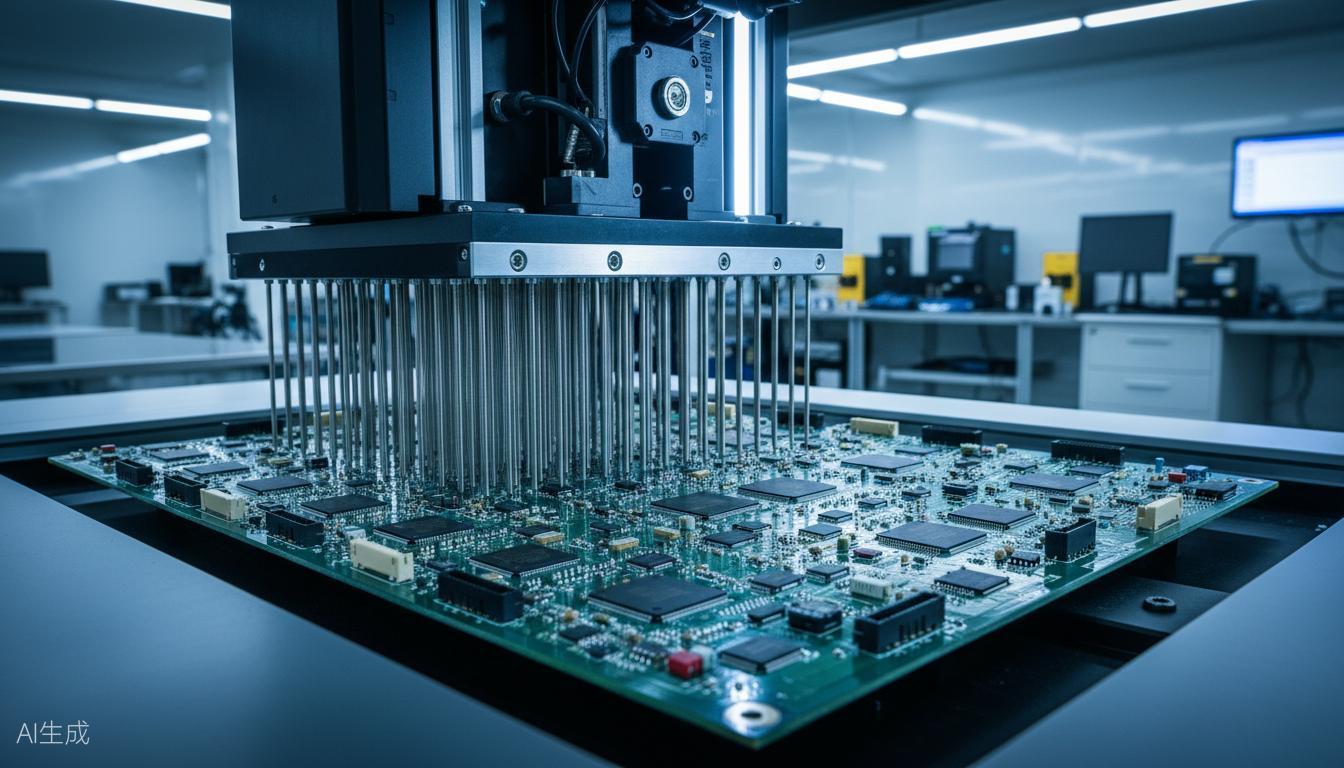
ICT and FCT have different jobs
ICT, or In-Circuit Test, checks the board at circuit level. It can detect open circuits, shorts, wrong values, missing components, reversed diodes, power-net problems and some IC soldering defects. It depends on test points, bed-of-nails fixtures, access rules and a stable test program. ICT is useful because it finds many manufacturing defects before the board reaches final function testing.
FCT, or Functional Circuit Test, verifies how the assembled PCBA behaves as a product. It may test power-up sequence, communication, display, sensors, relays, motor output, charging, wireless connection, firmware response or load behavior. FCT is closer to customer use, but it is often weaker at locating the root cause. If a board fails a communication test, the cause could be soldering, firmware, clock, power, connector, component damage or test fixture error.
The correct question is not whether ICT or FCT is better. The correct question is which defect each method is expected to catch. A serious DFT plan maps expected defects to test method, failure code and repair path.